


two mirrors, but a third image I3 is also present, formed by sequential reflections from both mirrors. All parts of Figure 3-14 and the related discussion above should be understood clearly because they are fundamental to the optics of images. Look at Example 5.
Example 5
Making use of the law of reflection and the conclusions drawn from Figure 3-14, draw the image of the letter L positioned above a plane mirror as shown below in (a). 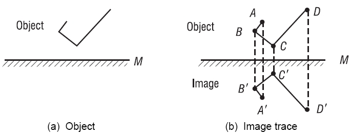
Solution: Make use of the fact that each point on the image is as far below the mirror—along a line perpendicular to the mirror—as the actual object point is above the mirror. Indicate key points on the object and locate corresponding points on the image. Sketch in the image as shown in (b).
B. Images formed with spherical mirrors
As we showed earlier in Figure 3-6, the law of reflection can be used to determine the direction along which any ray incident on a spherical mirror surface will be reflected. Using the law of reflection, we can trace rays from any point on an object to the mirror, and from there on to the corresponding image point. This is the method of graphical ray tracing.
1. Graphical ray-trace method To employ the method of ray tracing, we agree on the following:
- Light will be incident on a mirror surface initially from the left.
- The axis of symmetry normal to the mirror surface is its optical axis.
- The point where the optical axis meets the mirror surface is the vertex.
To locate an image we use two points common to each mirror surface, the center of curvature C and the focal point F. They are shown in Figure 3-15, with the mirror vertex V, for both a concave and a convex spherical mirror.
Page: 12345678910111213141516171819202122232425262728293031323334353637383940
| Eyes carePhysicianBate's booksLaser corre.Blues under eyesburning in the eyesanother diseasesMedical mistery Naturally eyesight correction. No laser eye surgery. Restore eyesight. Vision correction. |