As we have seen, Gaussian optics—sometimes called paraxial optics—arises from the basic approximations sin φ =~ ϕ, tan φ =~ ϕ , and cos φ =~ 1. These approximations greatly simplify ray tracing and lens formulas, but they do restrict the angles the light rays make with the optical axis to rather small values of 20° or less.
B. Types of lenses
If the axial thickness of a lens is small compared with the radii of curvature of its surfaces, it can be treated as a thin lens. Ray-tracing techniques and lens formulas are relatively simple for thin lenses. If the thickness of a lens is not negligible compared with the radii of curvature of its faces, it must be treated as a thick lens. Ray-tracing techniques and lens-imaging formulas are more complicated for thick lenses, where computer programs are often developed to trace the rays through the lenses or make surface-by-surface calculations. In this basic introduction of geometrical optics, we shall deal with only thin lenses.
1. Converging and diverging thin lenses.
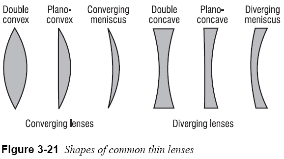
In Figure 3-21, we show the shapes of several common “thin” lenses. Even though a “thickness” is shown, the use of thin lenses assumes that the rays simply refract at the front and rear faces without a translation through the lens medium. The first three lenses are thicker in the middle than at the edges and are described as converging or positive lenses. They are converging because they cause parallel rays passing through them to bend toward one another. Such lenses give rise to positive focal lengths. The last three lenses are thinner in the middle than at the edges and are described as diverging or negative lenses. In contrast with converging lenses, they cause parallel rays passing through them to spread as they leave the lens. These lenses give rise to negative focal lengths. In Figure 3-21, names associated with the different shapes are noted.
Focal points of thin lenses.
Just as for mirrors, the focal points of lenses are defined in terms of their effect on parallel light rays and plane wave fronts. Figure 3-22 shows parallel light rays and their associated plane wave fronts incident on a positive lens (Figure 3-22a) and a negative lens (Figure 3-22b). For the positive lens, refraction of the light brings it to focal point F (real image) to the right of the lens. For the negative lens, refraction of the light causes it to diverge as if it is coming from focal point F (virtual image) located to the left of the lens. Note how the plane wave fronts are changed to converging spherical wave fronts by the positive lens and to diverging spherical wave fronts by the negative lens. This occurs because light travels more slowly in the lens medium than in the surrounding air, so the thicker parts of the lens retard the light more than do the thinner parts. 
Page: 12345678910111213141516171819202122232425262728293031323334353637383940
| Eyes carePhysicianBate's booksTechnologyForumLaser corre.Blues under eyesburning in the eyesanother diseasesMedical mistery Naturally eyesight correction. No laser eye surgery. Restore eyesight. Vision correction. |


