


The behavior of rays 1 and 2—connected with the left and right focal points for both the positive and negative lenses—should be apparent from another look at Figure 3-23. The behavior of ray 3—going straight through the lens at its center V—is a consequence of assuming that the lens has zero thickness. Note, in fact, that, for both Figures 3-23 and 3-25, all the bending is assumed to take place at the dashed vertical line that splits the drawn lenses in half. Also, it should be clear in Figure 3-25 that the positive lens forms a real image while the negative lens forms a virtual image.
One can apply the principles of ray tracing illustrated in Figure 3-25 to a train of thin lenses. Figure 3-26 shows a ray trace through an “optical system” made up of a positive and a negative lens. For accuracy in drawing, a common practice used here is to show the positive lens as a vertical line with normal arrowheads and the negative lens as a vertical line with inverted arrowheads, and to show all ray bending at these lines. Note that the primary object is labeled RO1 (real object 1) and its image formed by the positive lens is labeled RI1 (real image 1). The image RI1 then serves as a real object (RO2) for the negative lens, leading finally to a virtual image VI2.
Test your understanding of ray tracing through thin lenses by accounting for each numbered ray drawn in the figure. What happens to rays 1 and 3 relative to the negative lens? Why are rays 4 and 5 introduced? Is this a “fair” practice? 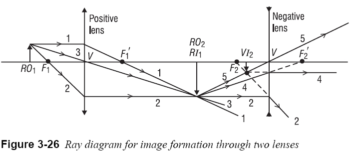
D. Lens formulas for thin lenses
As with mirrors, convenient formulas can be used to locate the image mathematically. The derivation of such formulas—as was carried out for spherical mirrors in the previous section— can be found in most texts on geometrical optics. The derivation essentially traces an arbitrary ray geometrically and mathematically from an object point through the two surfaces of a thin lens to the corresponding image point. Snell’s law is applied for the ray at each spherical refracting surface. The details of the derivation involve the geometry of triangles and the approximations mentioned earlier sin ɸ≅φ, tan ϕ≅φ, and cos ϕ≅ 1 1—to simplify the final results. Figure 3-27 shows the essential elements that show up in the final equations, relating object distance p to image distance q, for a lens of focal length f with radii of curvature r1 and r2 and refractive index ng. For generality, the lens is shown situated in an arbitrary medium of refractive index n. If the medium is air, then, of course, n = 1.
Page: 12345678910111213141516171819202122232425262728293031323334353637383940
| Eyes carePhysicianBate's booksLaser corre.Blues under eyesburning in the eyesanother diseasesMedical mistery Naturally eyesight correction. No laser eye surgery. Restore eyesight. Vision correction. |