outside the prism. On the paper, trace the edges of the prism, a line along the incident beam, a line along the path through the prism, and a line along the exit beam. Label the angles of incidence and reflection and their values at the face where TIR takes place. What would you need to know to determine the critical angle at this face? Is the incident angle on the face where TIR occurs larger or smaller than the critical angle?
2 Move the right-angle prism to a different position on the 11" × 17" paper and tape it down. Direct the diode laser beam onto an appropriate face so that the beam returns along a direction parallel to its entering direction. Use index cards to “locate” the beam path. When you have achieved this condition of retroreflection, trace the edges of the prism, the entering beam, the path through the prism, and the exit beam. Draw appropriate angles at the faces where TIR occurs and give their correct values.
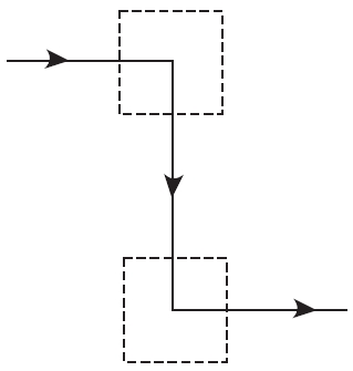
3. Move two right-angle prisms to a new location on the 11" × 17" paper. Arrange them to produce “periscope action.” This action requires, for example, that a horizontal beam that enters at one level be deflected downward 90° and exit horizontally at a different level, as shown in the accompanying sketch. Here the dashed squares indicate the locations of the two prisms. Use index cards to locate the beam through the prism arrangement.
When you have achieved the “periscope” geometry, tape the prisms down. Trace their edges, and trace the laser beam path from initial entry to final exit. Show where TIR occurs and label the incident and reflected angles there correctly, at each position. 
C. Index of Refraction of a Thin Lens
Use the lensmaker’s equation
to determine the value of ng for the double-convex lens. Use a ruler, overhead lights, and an index card to obtain a good approximation for the focal length of the lens. (Going outside and imaging the sun would be even better.) Use a spherometer to measure the radii of curvature r1 and r2. (You will have to be especially creative to get r1 and r2 if you don’t have access to a spherometer.) With the values of f, r1, and r2, solve the lensmaker’s equation for ng, the index of refraction of the lens glass. Compare your value with values given in Table 3-1. Do you have a match?
D. Measuring the Focal Lengths of Thin Lenses
Set up the two diode lasers on a stand or optical bench so that they emit beams parallel to one another and normal to the plane defining the vertical position of the thin lens. See Figure L-2. (To see the beams converging on the image side of the lens, you will have to use chalk-dust particles or smoke—some form of cloud—to illuminate the path.) By moving the screen forward and backward, you can locate a position where the beams cross to form the “smallest” spot. This is the focal
Page: 12345678910111213141516171819202122232425262728293031323334353637383940
| Eyes carePhysicianBate's booksTechnologyForumLaser corre.Blues under eyesburning in the eyesanother diseasesMedical mistery Naturally eyesight correction. No laser eye surgery. Restore eyesight. Vision correction. |


